Monday, 29 April 2019

Term 1 Holidays Update: Engine Fixed, Paint Work

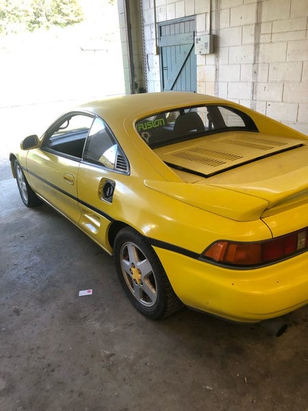
Over the holiday break, we got the Toyota MR2 checked at Pacific Toyota which came back good as the engine was assessed in good condition, which meant recovering costs would be easier. They said some sort of faulty wiring or reading error to the ECU was causing it to run rough.

Anyway, I went and checked all the fluids, oil was changed a couple weeks ago and I changed/flushed the coolant. I wanted to get the engine running well before selling so I went and tested all the sensors around the engine bay according to the service manual, and found the water temp, air intake temp, engine bay temp were all going well, spark plugs were firing correctly. I came to the vacuum sensor, where I noticed it had a missing vacuum line which I made a little tube to connect it properly. I then went and cleaned out the spark plugs which were completely charred up again with carbon preventing it from starting. I filled it up with some 91 petrol, to which it began to idle now but still misfiring a bit. On restarting the engine, it ran amazing, very little exhaust gas was being expelled and the vacuum sensor seemed to be operating correctly which was awesome. I have since listed the engine and some other parts on Trade Me to get them sold off to begin the conversion. I will also be getting a rust repair on the sills done so I can get the car a warrant of fitness and road legal before I begin.

I also did a lot of little spot repairs, cleaned out some rust underneath then primed and painted it. I also cleaned out each wheel well, attaching a loose mudguard, cleaning out rust spots and painting black, plus doing the brake calipers red for a nice clean finishing look. I also did each rim with tires on a black color which looks a lot better aesthetically and my stakeholder Anna really liked.


Another thing I added in is a hydraulic boot opening piston thingy I found at CREW for $1. I made a couple adapter brackets riveted to the body and it now works well.


Over the holiday break, we got the Toyota MR2 checked at Pacific Toyota which came back good as the engine was assessed in good condition, which meant recovering costs would be easier. They said some sort of faulty wiring or reading error to the ECU was causing it to run rough.

Anyway, I went and checked all the fluids, oil was changed a couple weeks ago and I changed/flushed the coolant. I wanted to get the engine running well before selling so I went and tested all the sensors around the engine bay according to the service manual, and found the water temp, air intake temp, engine bay temp were all going well, spark plugs were firing correctly. I came to the vacuum sensor, where I noticed it had a missing vacuum line which I made a little tube to connect it properly. I then went and cleaned out the spark plugs which were completely charred up again with carbon preventing it from starting. I filled it up with some 91 petrol, to which it began to idle now but still misfiring a bit. On restarting the engine, it ran amazing, very little exhaust gas was being expelled and the vacuum sensor seemed to be operating correctly which was awesome. I have since listed the engine and some other parts on Trade Me to get them sold off to begin the conversion. I will also be getting a rust repair on the sills done so I can get the car a warrant of fitness and road legal before I begin.

I also did a lot of little spot repairs, cleaned out some rust underneath then primed and painted it. I also cleaned out each wheel well, attaching a loose mudguard, cleaning out rust spots and painting black, plus doing the brake calipers red for a nice clean finishing look. I also did each rim with tires on a black color which looks a lot better aesthetically and my stakeholder Anna really liked.

Sunday, 28 April 2019

WEEK 11: Battery Research, Fixing Car

This week I started working on energy storage for the electric car. Batteries which store chemical potential energy are required to produce electrical energy in order to power the electric motor. I will begin looking into all the different types of batteries (as there are a lot out there).
For example there are lead acids, lithium ion, lithium polymer, nickel cadmium, nickel metal hydride, etc. each with their own benefits and downsides which I will get into next term.

On the car, I managed to replace a rocker gasket in the engine. My stakeholders Anna and Peter Stoove said it would be a really good idea to get the car warranted and running good before I start the project. I will be working on the little rust spots and paintwork through the holidays and we are getting a check at Pacific Toyota. I will also try to get the engine running well before I pull it out and get the parts listed on TradeMe.

Monday, 8 April 2019

Week 10: Clutch hydraulics + Painting

This week I worked on finishing my electric motor research to determine the best types of motor to use. I found that the BLDC and DC permanent/series or shunt wound motor would be the most effective in this project in terms of cost, power and efficiency. In mechanical engineering class, I am working on designing and building the electric motor to reduce costs and to design to fit my application of an electric car.

With some help I also managed to fix the hydraulics in the clutch system, but there is still a compression issue in the master cylinder which needs to be sorted out as the actuator slips when the pedal is moved slightly till the clutch is engaged which makes take off very difficult.

Apart from that, I worked on sanding down some rust spots and body filler on many areas of the paint. I then spray painted with the cars colour to patch up these spots which it looks way better now.


Monday, 1 April 2019

WEEK 9: Away

This week I was away on tournament so did not get any work done.
However, last weekend I did manage to do some work in the new Toyota MR2 which was quite a bit of fun.

We had no luck with the clutch hydraulics, but will try again next week. I mostly did a bit of cleaning and fixed up small things like loose bolts and covered up a couple rust spots so I can repair them later Anyway I will get back onto it next week.


WEEK 8: New Car + Finishing motor research


This week I also had a very exciting purchase of the Toyota MR2 1993 for $1.5K. We are planning to tow it here on the weekend so I can get to work on it quickly before I leave next week for tournament.

I then continued researching motor types and assessing their suitability for use in an electric car. Here is what I found:


Single/Three Phase AC Induction Motors:


Single and 3 phase AC induction motors a completely different design to DC motors.
They are designed to run off of a single or 3 phase alternating current which is typically found in household outlets (single phase AC) and industrial power (3 phase AC).


Single phase AC is simpler, having a neutral wire and single phase wire (and ground for household safety). The waveform from single phase line generally follows a clean sine wave curve alternating from positive to negative voltage, where 1 wavelength occurs per 360o rotation.


3 phase electricity is more complex and consists of multiple sine waves each spaced out 120o out of phase from each other.


3 phase power is more efficient and powerful as greater energy transfer can be achieved . This requires more wires for electricity transfer but is better for power output with additional phases.


Induction motors work from the principles of induction and electromagnetism, and were invented by Nikola Tesla. The field coils on the outer area of the motor have the input alternating current into them. The placement of these electromagnets in the outer stator generates a rotating magnetic field (around the rotor).


The rotor acts as a closed wire loop. A squirrel cage rotor (in common squirrel cage induction motors) is a cylinder of stacked steel laminations, with a conductive, non-ferromagnetic material in between such as aluminium or copper bars.
When the varying magnetic field rotates around the rotor (a closed conductor), Faraday’s law states an EMF (electromotive force) will be induced, causing the rotor to become a current carrying loop. When electric current flows in a loop, Lorentz force law shows a force will be applied to the rotor, causing it to rotate. The magnetic field rotates at a speed known as the synchronous speed, which is determined by the frequency of the power source. The rotor in an induction motor is always trying to catch up to the synchronous speed, but their will always be a slip (percentage less) speed. In a perfect world example with no energy losses, the rotor speed would equal synchronous speed, however there is always friction and resistance inefficiencies in motors, therefore the rotor will rotate slower than the rotating magnetic field (NROTOR < NSYNCHRONOUS SPEED). For example, slip amount could be 5%, but will increase greatly with more mechanical load. However with increased load there will be more torque produced from the rotor due to increased power/current flow provided to the field coils - this happens due to the EMF in to field coils being much greater than EMF back from rotor’s induced current, leading to a greater potential difference in voltage and a greater current being drawn into the motor’s field coils.


Speed (RPM) of an induction motor is therefore determined by the input frequency (determining synchronous speed), and will decrease with increased mechanical load on the rotor output shaft.


Induction motors are very versatile and are a favourite for industrial purposes because of their low maintenance (no brushes) no permanent magnets (less cost) and ease of control on single and 3 phase AC power. However, in order to achieve different speeds, a variable frequency drive (VFD) is required, which are more complex and costly to build or purchase, particularly a produce 3 phase producing controller.
Induction motors are also more difficult to use as generators compared to typical DC and BLDC permanent magnet motors, as the field coil must have an input synchronous speed slower than the rotor speed. But it is still possible to achieve power regeneration with proper electrical controls, which is an important feature for a more efficient vehicle braking system.

(Learn Engineering - YouTube, 31/08/17)


Brushless DC Motor (BLDC):

A brushless DC motor is similar to a DC motor, however the rotor consists of permanent magnets, which revolve around a stator with magnetic field generating coils.
The difference is instead of a brushed electromagnet setup in a DC motor, there are no brushes which a controller has to sense and apply current into each set of coils strategically. The coils are placed in a 3 phase arrangement. So when used as a generator, this type of motor will actually generate a 3 phase sine wave alternating current.
An efficient controller will actually use a 3 phase sine wave input but this has to be in time with the rotor.
If the coils were labelled as A, B and C, and the north pole of the permanent magnets were attracted when each coil were energised, a pattern occurs with the input current which is demonstrated in the graph below.


The controller is able to detect the rotor position by an effect of when magnets pass over coils called back EMF. When the controller detects this from a certain set of coils, it sends current to energise the next set of coils just before the rotor catches up to the previous set (last phase energised). When this pattern of electrical control continues, it is possible to achieve any desired speed of the rotor (assuming enough torque). As seen on the graph, the torque output is less even when a square wave signal is used. Therefore, by using a sine wave input current for these 3 phase coils, it is possible to achieve smooth acceleration and torque output of the rotor. This also generates less noise as the square signal typically clicks when each coil is energised.


A BLDC motor can also easily act as a generator to recharge batteries when braking. By rectifying the 3 phase current produced, the electricity can be sent back to the batteries to increase the efficiency of the vehicle.

Another positive is the efficiency is typically very good.

WEEK 7: Researching Electric Motors + Cars

This week, I began to look into all the different types of electric motors that could be used to propel an electric car.
These are the different motor types I found:


  • DC Brushed Motor (series/shunt)
  • Permanent Magnet DC Motor
  • Single Phase Induction Motor
  • 3 Phase Induction Motor
  • Brushless DC (BLDC) Motor
  • Stepper Motor

I found each has their own advantages and disadvantages for use in an electric car. Here is some stuff I researched: 


DC Brushed Motor (series/shunt):


As stated before DC motors use a DC current source, this could be from a constant voltage source like a DC wall adapter or a battery, etc. This is the most simplest motor type to power as it can come straight from a DC energy storage like batteries.

However, a DC motor construction uses a mechanical commutator to invert the DC power source for the stator coils to get an AC current. With series and shunt wound DC motors, the field coils are electromagnets that are either wound in series or parallel with the DC voltage source to create the magnetic field to cause the rotor to rotate. These motors have carbon brushes which are designed to wear to protect the commutator, so these will have to be serviced and replaced sometimes. Another downside is the increased friction and less possible RPM because of arcing at high speeds and friction/resistance losses to heat. But on the upside, DC motors are very simple to control and RPM scales with increased voltage and more torque is achieved by increased current. These give DC motors an advantage over simplicity but at a cost of efficiency and service life.

Permanent Magnet DC Motor:


These are the same to series/shunt DC motors but instead of electromagnetic fields they are created from permanent magnets (generally ferrite/ceramic for cheaper cost). These are simpler to series and shunt DC motors due to not having to power a field coil as well as the rotor. The magnetic field is fixed by the strength of the magnets, therefore a maximum torque spec is produced. Torque is determined by magnetic flux per pole (coils) of the rotor, from voltage and current, and the strength of the magnetic field. Some advantages include the simpler working mechanism, but still the friction of carbon brushes on the commutator causes less efficiencies. The permanent magnets (particularly in large DC motors) begin to take up a lot of weight and space to achieve good magnetic properties. This also begins to cost more and mould the magnets into the right shape. Therefore most larger DC motors are typically series or shunt wound (no magnets). This helps reduce weight and the electromagnetic field can be increased by variation in voltage and current to achieve better torque spec than typical permanent magnet DC motors.

Also there are several cars I have looked into so far on TradeMe:

- Mazda Lantis 1994:
 Located in Auckland:
Uses Manual Transmission
Has failed water pump - would require towing
Rego on hold, No WOF
Body in fair shape, clear coat peeling in places.

Cost would be approximately just over $1000 in total with towing, but would require a fair drive and fuel burnt to tow the car back here in Whakatane.


- Toyota MR2 1993:
Located in Whakatane (within a km)
Uses Manual Transmission
Engine is rough and running rich
Rego on hold, no WOF
Paint fading a little, primer in places, couple rust spots
Cost will probably end up around $2000 (auction) but may be less if I am lucky.

This car would be ideal to get and has a low profile and has a relatively efficient design.
The car is located a street away which makes transport very simple and no cost.